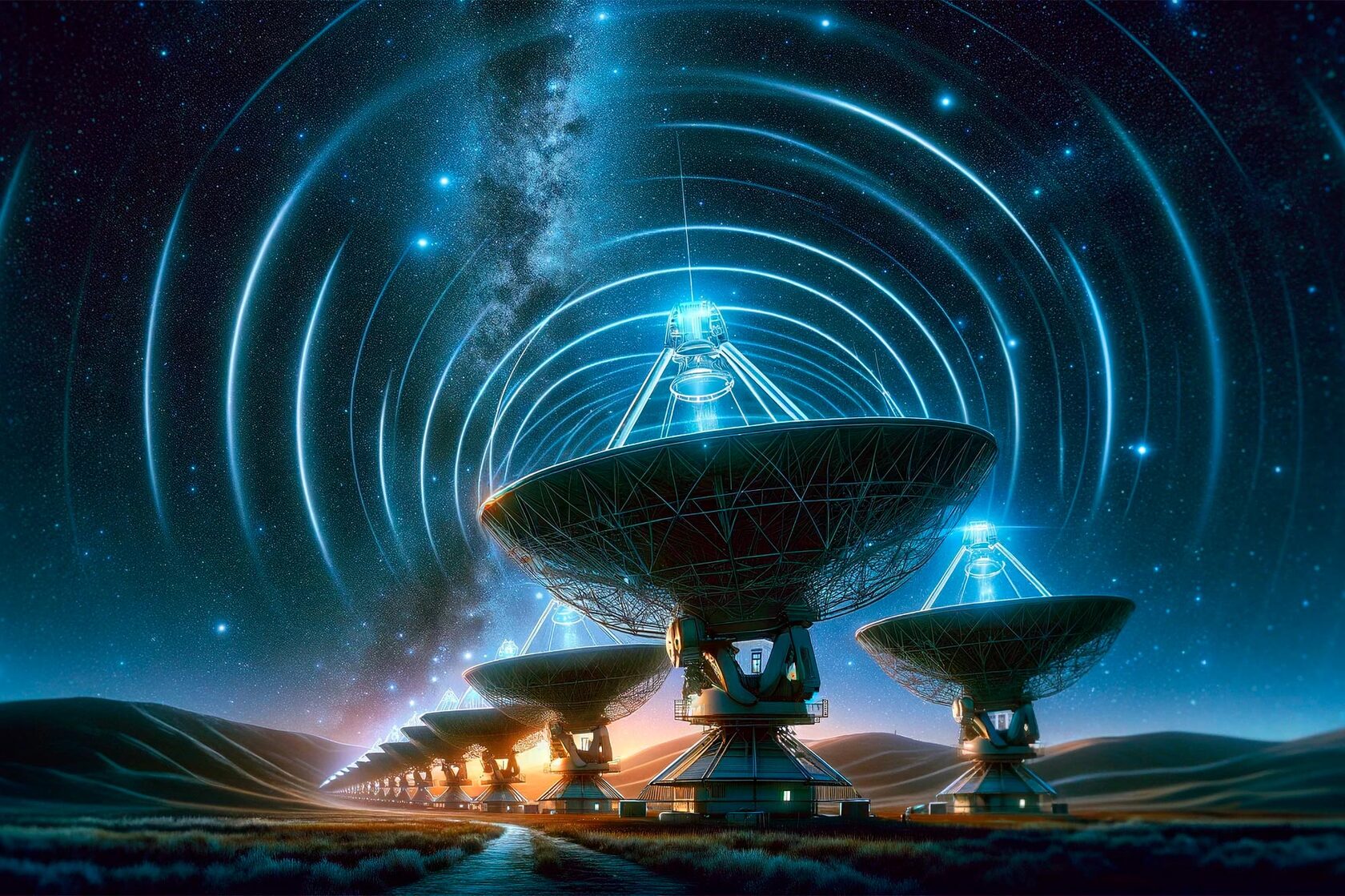
An experimental solution to the SETI problem, direct inclusion and documentation of the experimental network, receiving and processing signals.
Search for extraterrestrial intelligence
How to search for Alien civilization (SETI) to find it?
The channel is dedicated to an experimental solution to the SETI problem, direct inclusion and documentation of the experimental network, receiving and processing signals. Our team is determined to work continuously, evaluate solutions and correct technical errors, as well as erroneous decisions.
Documentation and observation of each experiment carried out is aimed at monitoring a conscientious attitude towards this decision, and routine research, as we know, is quite “boring and drawn-out”, so you can either join us or simply wait for the positive results of the study, and only then get acquainted with it with the entire set of previously conducted experiments.
Our experimental team took a slightly different path to solve this problem. I graduated from the Department of Experimental Physics and have already defended my PhD thesis, but in the field of machine learning and statistics, so the founders of this observation are physicists, mathematicians, and laser scientists.
Our concept says that it is much closer than we think, and some of them want to be heard, but the alien seekers are “doing everything wrong.”

Brief theory on in quantum and laser physics.
How do humans try to communicate with aliens?
We have developed a technique and corresponding software for restoring the so-called true signal using computer experiment methods.
Consider direct and inverse problems of spectroscopy - modeling and restoration of distorted (smoothed by hardware function, overlapping, noisy) spectra.
For the qualitative and quantitative research of substances, spectral analysis is used.
It consists in measuring signal and / or spectrum and in their processing, and then in diagnostics defects in machinery and equipment, determination of the composition of the
substance, temperature, density, pressure, etc. based on study measured and processed spectra.
Spectral analysis can be divided into broadband (study spectrum in a wide frequency band) and narrowband (study of fine structures of one line), as well as atomic, molecular,
emission, absorption, qualitative, quantitative, etc.
The spectrum means the dependence of the radiation intensity from wavelength or frequency.
In this case, the spectrum in mechanics is understood as the distribution of values some physical quantity (for example, vibration accelerations, vibration velocities, etc.).
It should be noted that the spectra are characteristic for all oscillatory processes: rotating around the core electron, etc. In optics, in particular, the spectrum is understood as
frequency dependence of radiation (or absorption) intensity or wavelength. To decompose radiation into a spectrum and register it, optical spectral instruments.
Each such device consists of three main parts: lighting (optional part), spectral and recording. Depending on the method spectrum registration is distinguished by the following
devices:
- spectroscopes (with visual registration);
- spectrometers, etc.
The spectrum can be obtained in the following ways: by the decomposition of a light beam as it passes through a prism (in prism spectroscopes), by calculating the Fourier
transform of two interfering rays (in Fourier spectrometers), etc.
In fig. 1 shows the principle of operation of the prism spectroscope

Light beams containing components with different wavelengths pass through the slit,
through the objective (lens) of the collimator (collimator is a device for obtaining parallel beams), and also through the prism and undergo two refractions in the prism (at entering and exiting the prism). Moreover, the coefficient refraction depends on the wavelength (the longer the wavelength, the less refraction), therefore, when passing through the prism, each the ray is decomposed into a series of rays with different wavelengths and in the result (after passing the rays through the focusing lens camera), the output is a spectrum - the intensity dependence light from wavelength. In fig. 2 introduces the principle work of the Fourier spectrometer.
through the objective (lens) of the collimator (collimator is a device for obtaining parallel beams), and also through the prism and undergo two refractions in the prism (at entering and exiting the prism). Moreover, the coefficient refraction depends on the wavelength (the longer the wavelength, the less refraction), therefore, when passing through the prism, each the ray is decomposed into a series of rays with different wavelengths and in the result (after passing the rays through the focusing lens camera), the output is a spectrum - the intensity dependence light from wavelength. In fig. 2 introduces the principle work of the Fourier spectrometer.

A Fourier spectrometer does not use a prism. Light from source after passing through
the collimator lens, it is divided into two beams using a translucent beam splitter. Then
one of beams are reflected from a stationary mirror, and the other is reflected from
movable mirror. Moving the movable mirror allows change the path difference of the
beams. Further, both beams are connected in photodetector, where they interfere and
get information terferogram (signal intensity as a function of the path difference of two
beams). In conclusion, obtaining the spectrum as a function of wavelength or frequency is produced using the Fourier transform of interferograms in the computer.
By the nature of the distribution of the values of a physical quantity, spectra are continuous, discrete, striped and combined (Fig. 3).
- continuous, or solid (examples of continuous spectra are the spectra of molten metal, the sun, hot gas flow in a rocket nozzle, in a car exhaust pipe, etc., in in general, the
spectra of substances with increased density);
- discrete, or line, spectrum consists of separate (monochromatic) spectral lines corresponding
to discrete wavelength (or frequency) values. Strictly speaking, an individual spectral line is not a discrete line, since it has, firstly, a minimum (natural, radiation) width, due to
quantum effects, secondly, the width due to the Doppler (thermal broadening), Zeeman (magnetic broadening), Stark (electrical broadening), diffraction on the diaphragms of
the optical system of the spectral device, etc.
However, if the line has only natural width, then usually it considered discrete (monochromatic).
Examples of discrete spectra are the
spectra of vibrational signals, the spectra of substances in deep vacuum, in particular, the
spectra of scattered interstellar nebulae, etc .;
- striped, consisting of a number of stripes, each of which, in its own turn, it consists of a set of similar discrete lines (example: spectra of substances in a shallow vacuum, in particular, spectra of fluorescent lamps and fluorescent lamps);
- complex, or combined, consisting, for example, of continuous spectrum and a number of discrete lines

Spectral Analysis
Spectral analysis can be divided into broadband and narrow band (as well as atomic,
molecular, emission, absorption, qualitative, quantitative, etc.).
Broadband spectroscopy is the study of a spectrum in a wide frequency range, for
example, studying the spectrum of a star in the entire visible range (from purple to red)
- see fig. 3 and 4a).
Narrow band spectroscopy is the study of a spectrum in a narrow band frequencies, for
example, the study of the hyperfine structure of the Mцssbauer lines due to magnetic or electric fields and thermal effects (Fig. 4 b).
However, the division into broad- and narrow-band spectroscopy is often conditionally.
Applications
Spectral analysis applications:
- physics (study of spectra of gases, liquids, metals and plasma, study of atomic
sensitized fluorescence of mixtures and vapors of metals along the contours of spectral lines, assessment of the magnetic or electric scorching on the superfine line structure based on Zeeman or Stark effect);
- astrophysics (study of the spectra of planets, stars, galaxies, nebulae, comets, quasars, relic radiation);
- metallurgy (determination by the spectrum of the state of the molten metal, for
example, in a blast furnace);
- chemistry and NMR(nuclear magnetic resonance) spectroscopy (determination by
NMR spectrum chemical composition of the substance); o geophysics (exploration of ores, minerals, oil, gas), etc.
Resolution of spectral instruments
The effectiveness of spectral analysis depends primarily on queue, on how high the resolution is the ability of a spectral instrument, namely, whether the instrument resolves close lines, does it highlight weak lines, does it identify superfine line structure, etc. If the resolution spectral device is insufficient, then the use of spectral analysis will be ineffective. However, if spectral measurements complement the mathematical and computer processing, you can increase the resolution spectral instrument, which we want to show in this chapter. The resolution of the spectral device, characterizing numerically the quality of spectral measurements, usually expressed by the formula.
The effectiveness of spectral analysis depends primarily on queue, on how high the resolution is the ability of a spectral instrument, namely, whether the instrument resolves close lines, does it highlight weak lines, does it identify superfine line structure, etc. If the resolution spectral device is insufficient, then the use of spectral analysis will be ineffective. However, if spectral measurements complement the mathematical and computer processing, you can increase the resolution spectral instrument, which we want to show in this chapter. The resolution of the spectral device, characterizing numerically the quality of spectral measurements, usually expressed by the formula.

Apparatus function of the spectral instrument

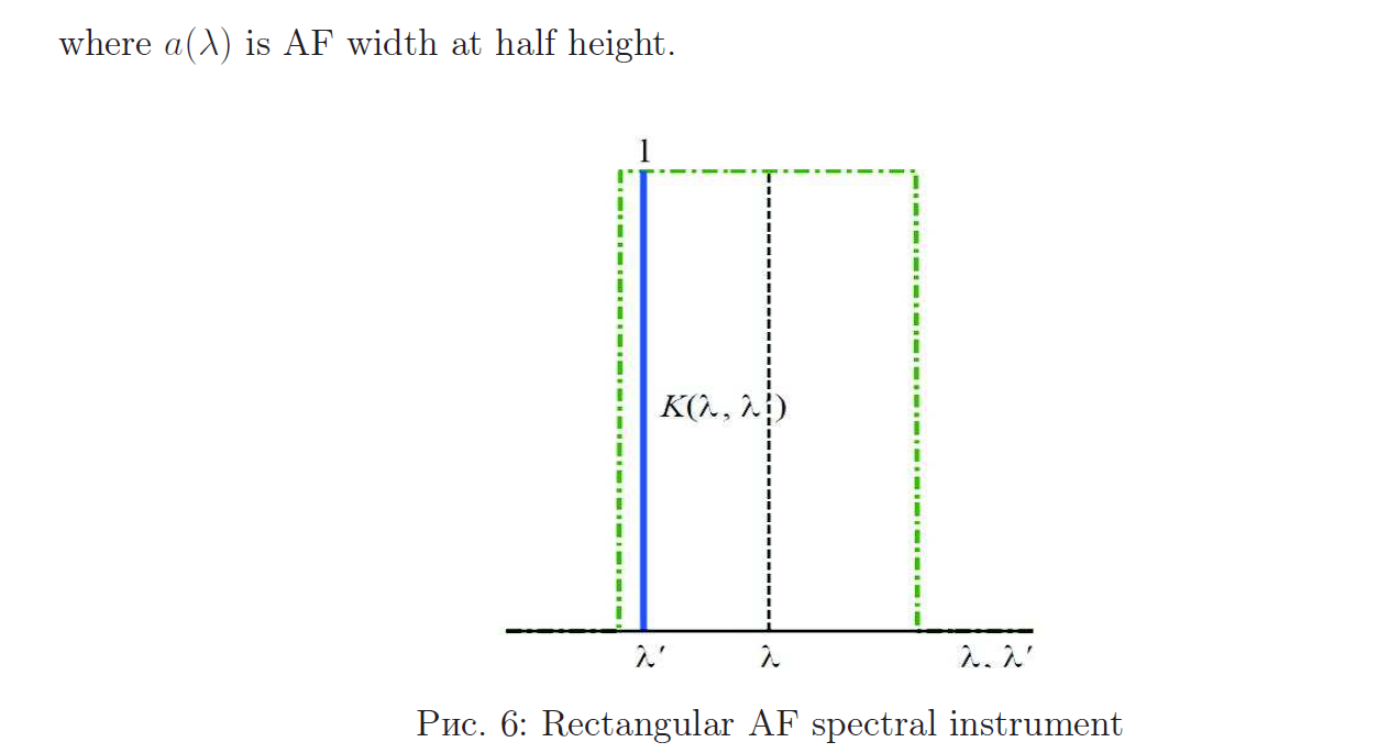
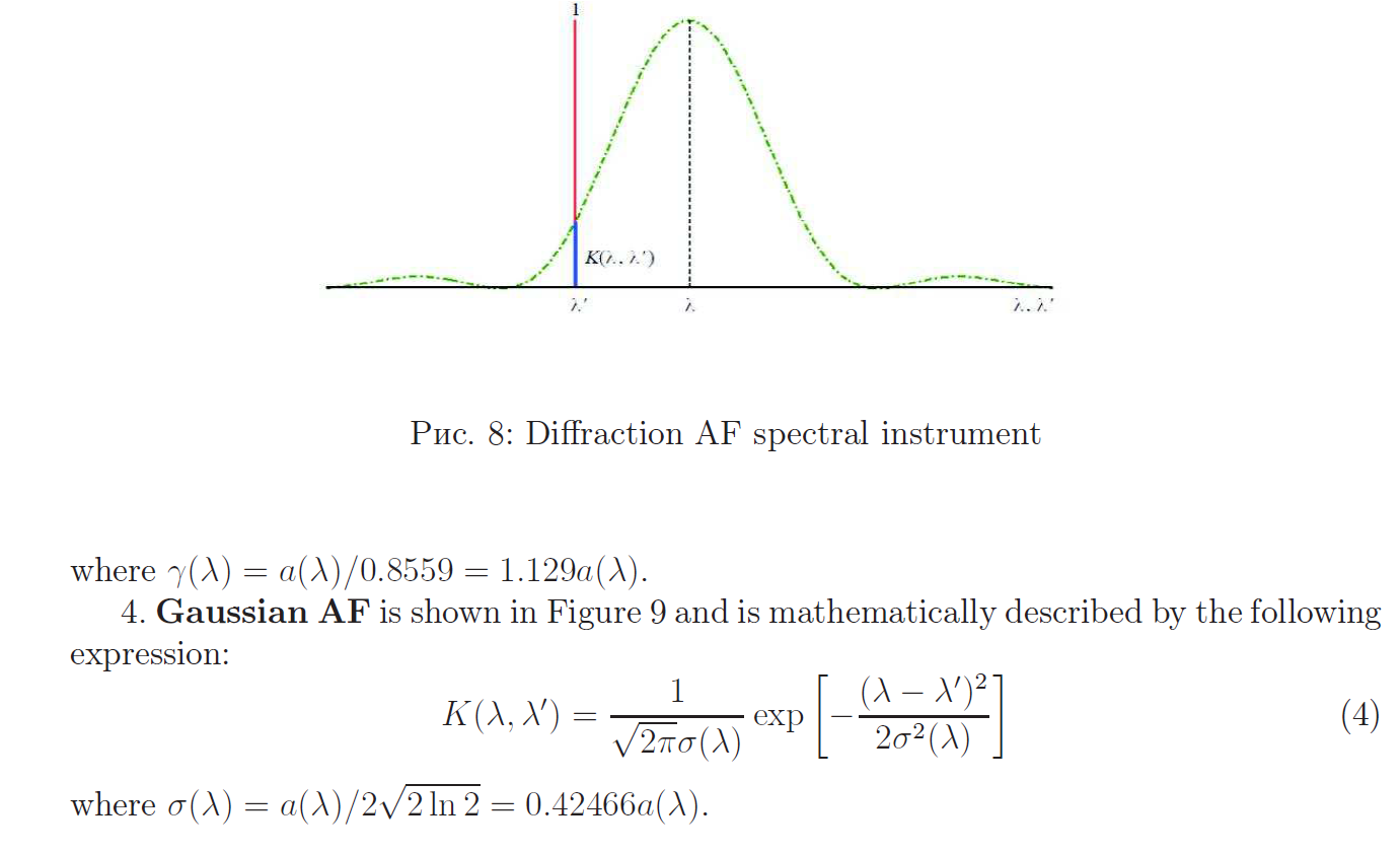
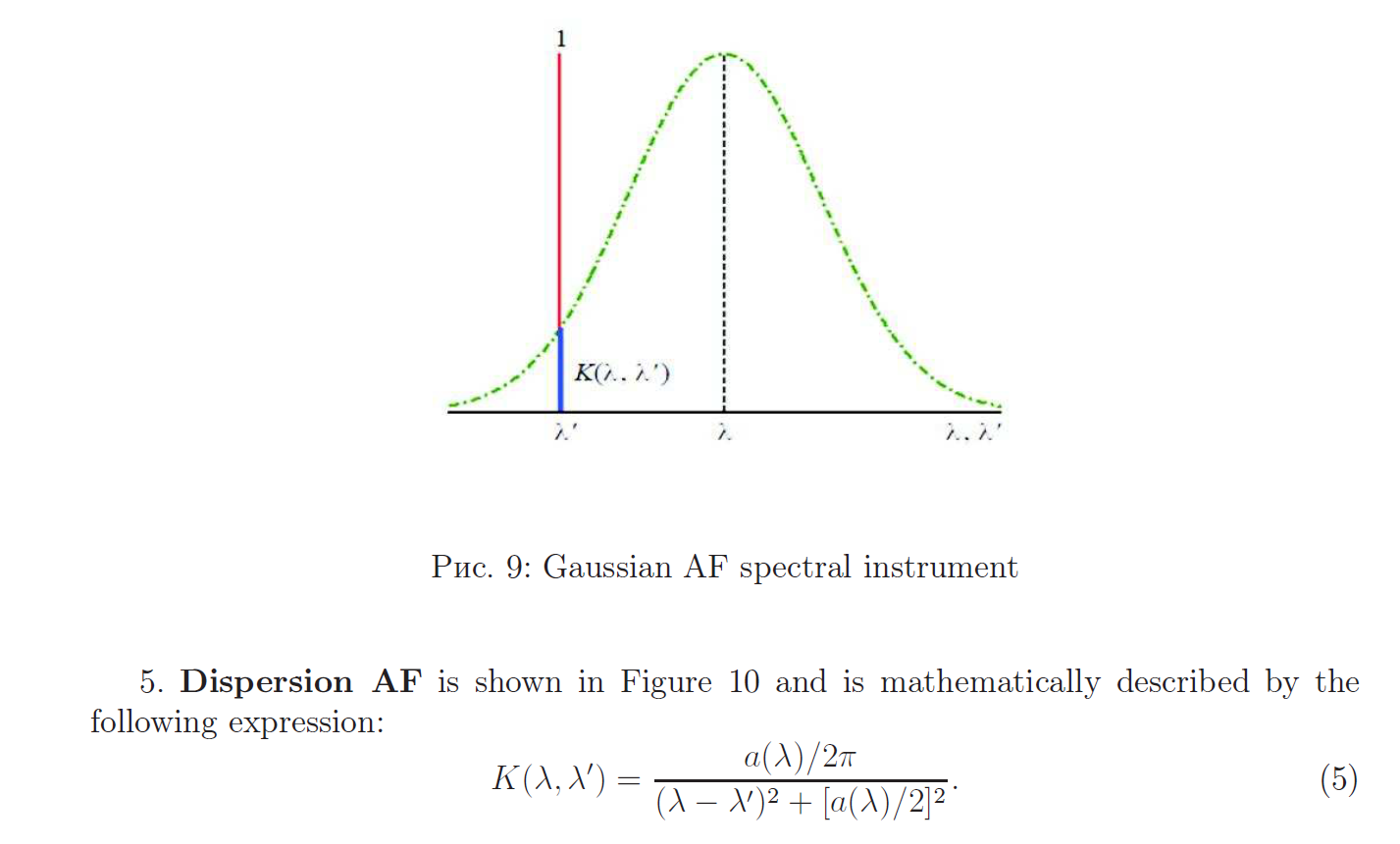

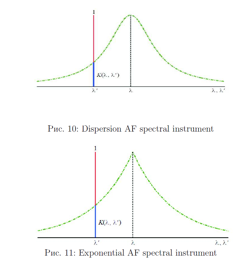
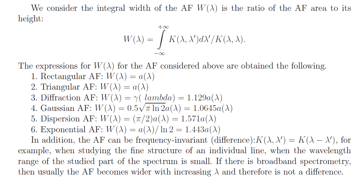
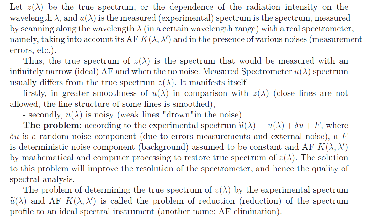
Reconstruction of continuous spectra using mathematical modeling
To study the developed technique for reconstructing continuous spectra, mathematical modeling of smoothed and noisy continuous spectra z(lambda) was carried out


Part 2
Electrical conductivity
Materials can be classified as conductors, semiconductors, or insulators based on their electrical conductivity. Conductors have high conductivity and allow electric current to flow easily, while insulators have low conductivity and do not allow current to flow. Semiconductors have conductivity values between those of conductors and insulators.
Electrical conductivity is denoted by the symbol σ and has SI units of siemens per meter (S/m). In electrical engineering, the Greek letter κ is used. Sometimes the Greek letter γ represents conductivity. In water, conductivity is often reported as specific conductance, which is a measure compared to that of pure water at 25°C.
Relationship Between Conductivity and Resistivity
Electrical conductivity (σ) is the reciprocal of the electrical resistivity (ρ):
σ = 1/ρ
where resistivity for a material with a uniform cross section is:
ρ = RA/l
where R is the electrical resistance, A is the cross-sectional area, and l is the length of the material. Electrical conductivity gradually increases in a metallic conductor as the temperature is lowered.
Materials With Good and Poor Electrical Conductivity
Examples of excellent conductors include:
- Silver
- Copper
- Gold
- Aluminum
- Zinc
- Nickel
- Brass
Potassium Iodide Solution Conduct Electricity
1pcs 99.9% Pure Resistivity
specific resistance, ρ, Ом*мм2/м:
Медь_______0,0175
Медь_______0,0175
The search for technosignatures is the most cost-effective way to search for life in the universe to detect extraterrestrial life was Frank Drake's SETI Project Ozma (1960), followed later by the Viking Landers on Mars (1976), and today by the James Webb Space Telescope (JWST) looking at the atmosphere of exoplanets, such as TRAPPIST-1.
Such radar transmissions are Earth-based and Earth-fixed. As Earth rotates and orbits about the Sun, these radars illuminate a haphazard portion of the celestial sphere in nearly inscrutable patterns. A remote observer would see a brief episode of very powerful pulses repeating at intervals of 1 Earth day. Attempts to decipher the presumed “message” would probably be unsuccessful: there is no message, but a sufficiently imaginative analyst might invent one! It is very likely that the diurnal variation would quickly be interpreted correctly as due to transmission from a planetary surface with a 24-h rotation period. Prolonged observation would reveal periodic Doppler shifts associated with both rotation and Earth's orbital motion. Integration of the Doppler shift over a day would reveal the radius of Earth (actually, the radius of the circle of latitude on which the transmitter lies), and over a year, the diameter (and period) of Earth's orbit, and hence the mass of the Sun.
7075 Aluminium Alloy Sheet Plate
specific resistance, ρ, Ом*мм2/м:
Aluminium_______0,028
Aluminium_______0,028
The traditional detection of biosignatures is very expensive and limited to a few locations, while technosignature projects are very inexpensive and able to sample a larger volume of the universe. That said, astrobiologists expect intelligent life to be much rarer than any other life form, which probably makes the detection of technosignatures much less likely than biosignatures. Nevertheless, it is surprising that we are not making all possible attempts to detect life in the universe. NASA decided to cancel SETI projects in the early 1990s. However, funding for SETI projects and more generally, any technosignature project was restored by NASA, starting with its Exobiology Program and the Exoplanet Research Program.
Interstellar communication is clearly technically feasible. The number of communicating civilizations in the Galaxy is of course wholly unknown, and therefore it is quite impossible to make meaningful statistical estimates of the mean distance between nearest-neighbor intelligent civilizations. How many stellar systems develop planets suitable for the origin of life? On how many of these do life forms arise? How many of these achieve intelligence? Of these, how many develop a technology capable of detection by others, or capable of detecting others? How long does it take for a communicating civilization to arise? How long does it last? Are advanced civilizations likely to destroy themselves shortly after achieving the technical ability to do so? Are they likely to give up relevant technologies voluntarily? Are they likely to achieve nondetectable communications technologies (closed laser circuits, fiber-optic cables, etc.) quickly, and hence abandon radio and television transmission? Will they be sufficiently paranoid—or realistic—to avoid emitting signs of their presence? Are there “berserkers” in space that seek out and destroy upcoming young technological civilizations as a means of self-protection? Are there star-faring civilizations that actually have the means to travel between stars? None of these questions can presently be answered.
99.995% Pure Iron Plate
Resistivity ρ, Ohm*mm2/m
Iron___0,1
Resistivity ρ, Ohm*mm2/m
Iron___0,1
For small radio astronomy projects, the capability to build or purchase such computing power is unaffordable, which is exactly the tradeoff they need to make. They can use a smaller computer instead of a large computer to work, but it will cost more time in this approach. It seems impossible that so much data could be analyzed in time. Fortunately, it is possible to break up the data analysis task easily into subtasks that are little pieces. And, these pieces can be processed separately and in parallel with no mutual intervention. In addition, the amount of sky that can be seen from Arecibo is finite. As such, the entire sky as seen from the telescope will be scanned three times in the next 2 years. Generally speaking, this will be enough for the project. New telescopes, new experiments, and new approaches will come forth to SETI by the time that the sky is scanned three times.
Pure Titanium Ti Thin Thick Plate Sheet Foil Strip
specific resistance, ρ, Ом*мм2/м:
Titanium _______0,6
specific resistance, ρ, Ом*мм2/м:
Titanium _______0,6
In 1978 the first “twin quasars” image, caused by the gravitational field of an intermediate galaxy, was spotted by astronomer Dennis Walsh and his colleagues (ref. 6) and subsequent discoveries of several more examples of gravitational lenses eliminated all doubts about gravitational focussing predicted by general relativity.
Brushed Stainless Steel Sheet Metal 304
Nowdays, this is the frequency that all radioastronomers doing SETI (the Search for ExtraTerrestrial Intelligence) regard as the #1 “magic” frequency for interstellar communications, and thus the tremendous potential of the gravitational lens of the Sun for letting humankind get in touch with alien civilizations became obvious. The first experimental SETI radioastronomer in history
99.9% Pure Copper Cu Metal Sheet Foil Plate
specific resistance, ρ, Ом*мм2/м:
Латунь_______0,025 - 0,108
specific resistance, ρ, Ом*мм2/м:
Латунь_______0,025 - 0,108
However, the possibility of planning and funding a space mission to 550 AU to exploit the gravitational lens of the Sun immediately proved a difficult task. Space scientists and engineers first turned their attention to this goal at the June 18, 1992, Conference on Space Missions and Astrodynamics organized in Turin, Italy, led by the author of this note. The relevant Proceedings were published in 1994 in the Journal of the British Interplanetary Society (ref. 12). Meanwhile (May 20, 1993) the author submitted a formal Proposal to the European Space Agency (ESA) to fund the space mission design (ref. 13). The optimal direction of space to launch the FOCAL spacecraft was discussed by Jean Heidmann of Paris Meudon Observatory and the author
99.96% Pure Nikel Strip
0.15x30mm
specific resistance, ρ, Ом*мм2/м:
Nikel_______0,087
0.15x30mm
specific resistance, ρ, Ом*мм2/м:
Nikel_______0,087
This is the minimal distance from the Sun that the FOCAL spacecraft must reach to get hugely magnified radio pictures of sources on the other side of Sun w.r.t. the spacecraft.
Furthermore, all points on the straight line beyond this minimal focal distance are foci too, because the light rays passing by the Sun further than the minimum distance have smaller deflection angles and thus come together at an even greater distance from the Sun. So, it is not necessary to stop the spacecraft at 550 AU. It can go on to any distance beyond and focus as well or better. In fact, the further it goes beyond 550 AU the less distorted the collected radio waves by the Sun Corona fluctuations.
Furthermore, all points on the straight line beyond this minimal focal distance are foci too, because the light rays passing by the Sun further than the minimum distance have smaller deflection angles and thus come together at an even greater distance from the Sun. So, it is not necessary to stop the spacecraft at 550 AU. It can go on to any distance beyond and focus as well or better. In fact, the further it goes beyond 550 AU the less distorted the collected radio waves by the Sun Corona fluctuations.
90% Pure Silver Strip (jewelry order)
0.15x70mm
specific resistance, ρ, Ом*мм2/м:
Silver_______0,015 (100% Silver strip)
0.15x70mm
specific resistance, ρ, Ом*мм2/м:
Silver_______0,015 (100% Silver strip)
A hypothetical observer at the galactic antipodes would receive these content-free signals after some 60,000 years of travel time. The logical response for the alien observer might be, “What? I don't understand you!” One fine Tuesday evening, 120,000 years after the original radar pulses were sent out from Earth, this complaint arrives at Earth. Will anyone be listening? Will anyone remember the original transmission? Will radio technology still be in use? Will anyone still live on Earth? Clearly, this is no way to establish a meaningful dialogue.
BASICS
What happens when photons hit metal?
When a photon hits the metal surface, the photon's energy is absorbed by an electron in the metal. The graphic below illustrates the relationship between light frequency and the kinetic energy of ejected electrons. The effects of wave frequency on photoemission.
Когда фотон попадает на поверхность металла, энергия фотона поглощается электроном в металле. График ниже иллюстрирует взаимосвязь между частотой света и кинетической энергией выброшенных электронов. Влияние частоты волны на фотоэмиссию.
Visual communication
When experiments were performed to look at the effect of light amplitude and frequency, the following results were observed:
- The kinetic energy of photoelectrons increases with light frequency.
- Electric current remains constant as light frequency increases.
- Electric current increases with light amplitude.
- The kinetic energy of photoelectrons remains constant as light amplitude increases.


If the photon has less energy than w, no electron is emitted.
If light with a photon energy hν that exceeds the work function W falls on a metal surface, some of the incident photons will transfer their energy to electrons, which then will be ejected from the metal. Since hν is greater than W, the excess energy hν − W transferred to the electrons will be observed as their kinetic energy outside the metal. The relation between electron kinetic energy E and the frequency ν (that is, E = hν − W) is known as the Einstein relation, and its experimental verification helped to establish the validity of quantum theory. The energy of the electrons depends on the frequency of the light, while the intensity of the light determines the rate of photoelectric emission.
Если на поверхность металла упадет свет с энергией фотонов hν, превышающей работу выхода W, часть падающих фотонов передаст свою энергию электронам, которые затем будут выброшены из металла. Поскольку hν больше W, избыточная энергия hν − W, передаваемая электронам, будет наблюдаться как их кинетическая энергия вне металла. Связь между кинетической энергией электрона E и частотой ν (т. е. E = hν − W) известна как соотношение Эйнштейна, и его экспериментальная проверка помогла установить справедливость квантовой теории. Энергия электронов зависит от частоты света, а интенсивность света определяет скорость фотоэлектрической эмиссии.
Electrons can be excited from the valence to the conduction band by light photons having an energy hν that is larger than energy gap Eg between the bands. The process is an internal photoelectric effect. The value of Eg varies from semiconductor to semiconductor
Электроны могут возбуждаться из валентной зоны в зону проводимости световыми фотонами, энергия hν которых превышает энергетическую щель Eg между зонами. Этот процесс представляет собой внутренний фотоэлектрический эффект. Значение Eg варьируется от полупроводника к полупроводнику.
Each transition yields a hole–electron pair (i.e., two carriers) that contributes to electric conductivity.
For example, if one milliwatt of light strikes a sample of pure silicon in the form of a thin plate one square centimetre in area and 0.03 centimetre thick (which is thick enough to absorb all incident light), the resistance of the plate will be decreased by a factor of about 1,000.
In practice, photoconductive effects are not usually as large as this, but this example indicates that appreciable changes in conductivity can occur even with low illumination. Photoconductive devices are simple to construct and are used to detect visible, infrared, and ultraviolet radiation.
Каждый переход дает пару дырка-электрон (т.е. два носителя), которая вносит вклад в электропроводность.
Например, если один милливатт света попадет на образец чистого кремния в виде тонкой пластинки площадью один квадратный сантиметр и толщиной 0,03 сантиметра (достаточно толстой, чтобы поглотить весь падающий свет), сопротивление пластины уменьшится. примерно в 1000 раз.
На практике эффекты фотопроводимости обычно не столь велики, но этот пример показывает, что заметные изменения проводимости могут происходить даже при низкой освещенности. Фотопроводящие устройства просты в конструкции и используются для обнаружения видимого, инфракрасного и ультрафиолетового излучения.
BASICS
Diode Green Lasers
Colour space diagram
The graph shows how a “Watt” of light of a given wavelength is perceived by human in terms of lumens. As the graph shows, a 532nm green has 603 lumens/Watt, whereas, 510nm green has only 344 lumens/Watt or about 57% the lumens/Watt of the 532 green. In between, 525nm green with 542 lumens per Watt or about 89% that of 532nm gre
The atomic energy level diagram of the green laser pointer is shown in Fig. N. Hereafter, we use the acronym GLP (Green Laser Pointer) to refer only to devices employing the diode-pumped,frequency-doubling architecture shown there.
Figure N exhibits three essential elements ofoperation, each of which was at its time a highlight of laser technology:a semiconductor pump diode laser operating at an infrared wavelength of 808 nma neodymium ion oscillator at a wavelength of 1064 nma frequency-doubling crystal that generates light of half of that wavelength, the Familia GLP color at 532 nm
Figure N exhibits three essential elements ofoperation, each of which was at its time a highlight of laser technology:a semiconductor pump diode laser operating at an infrared wavelength of 808 nma neodymium ion oscillator at a wavelength of 1064 nma frequency-doubling crystal that generates light of half of that wavelength, the Familia GLP color at 532 nm
Диаграмма уровней атомной энергии зеленой лазерной указки показана на рис. 1. Далее мы используем аббревиатуру GLP (зеленая лазерная указка) для обозначения только устройств, использующих показанную там архитектуру с диодной накачкой и удвоением частоты.
На рисунке 1 показаны три основных элемента работы, каждый из которых в свое время был выдающимся достижением лазерной технологии: полупроводниковый диодный лазер накачки, работающий на инфракрасной длине волны 808 нма, генератор на ионах неодима с длиной волны 1064 нма, кристалл с удвоением частоты, генерирующий свет. половины этой длины волны цвет семейства GLP при 532 нм
На рисунке 1 показаны три основных элемента работы, каждый из которых в свое время был выдающимся достижением лазерной технологии: полупроводниковый диодный лазер накачки, работающий на инфракрасной длине волны 808 нма, генератор на ионах неодима с длиной волны 1064 нма, кристалл с удвоением частоты, генерирующий свет. половины этой длины волны цвет семейства GLP при 532 нм

Figure N. Atomic energy levels and light involved in the operation of a GLP.
Figure N. Atomic energy levels and light involved in the operation of a GLP. Triply-charged ions of theneodymium atoms, Nd3+, are present as dopants in a crystal of yttrium orthovanadate (Nd:YVO4).
The Nd3+ ion contains three 4f electrons outside closed electron shells, so its electronic configuration is thus designated 4f 3.
The horizontal lines indicate some of the energy levels of the 4f 3 configuration, labeled by conventional spectroscopic notation. A semiconductor diode laser with an infrared wavelength of 808 nm excites the lowest 4I state to electronically excited 4F state.
The Nd3+ ion emits infrared radiation, at a wavelength of 1064 nm, as it drops fromthe excited state into a different 4I state. This radiation is directed into a “frequency doubling” crystal of potassium titanyl phosphate, which emits light of half the wavelength: 532 nm. Figure credit: Dr. Joseph Reader, NationalInstitute of Standards and Technology.
Рисунок N. Уровни атомной энергии и свет, участвующие в работе GLP. Трехзарядные ионы атомов неодима Nd3+ присутствуют в качестве легирующих примесей в кристалле ортованадата иттрия (Nd:YVO4). Ион Nd3+ содержит три электрона 4f вне закрытых электронных оболочек, поэтому его электронная конфигурация обозначается как 4f 3. Горизонтальные линии указывают на некоторые энергетические уровни конфигурации 4f 3, обозначенные обычными спектроскопическими обозначениями. Полупроводниковый диодный лазер с длиной волны инфракрасного излучения 808 нм возбуждает самое низкое состояние 4I в электронно-возбужденное состояние 4F. Ион Nd3+ излучает инфракрасное излучение с длиной волны 1064 нм, когда он переходит из возбужденного состояния в другое состояние 4I. Это излучение направляется в кристалл калийтитанилфосфата с «удвоением частоты», который излучает свет половины длины волны: 532 нм.

Figure M.
Schematic of the operation of a GLP
based on a Multiple Crystal Assembly (M
Schematic of the operation of a GLP
based on a Multiple Crystal Assembly (M
Figure M. Schematic of the operation of a GLPbased on a Multiple Crystal Assembly (MCA). The familiar external package contains two AAA batteries that power the unit, a printed circuit board with the pump Laser Diode (LD) driving circuitry and the Diode Pumped Solid State Laser(DPSS) Module.
The 808 nm pump LD is optically coupled to the Nd:YVO4 conversion crystal (violet section of the MCA), which emits 1064 nm light into the KTP frequency-doubling crystal (light blue section).
The 532 nm light from the KTP crystal is sent through an expanding and collimating lens assembly to produce a collimated output beam. In this configuration, an IR Filter prevents the 808 nm and 1064 nm light from exiting the laser.
In the GLP discussed in this paper, no such infrared filter was present. HR: High Reflectivity; HT:High Transmissivity; AR: Anti-Reflective; OC: Output Coupler; IR: InfraRed. This figure is the copyrighted work of Samuel M. Goldwasser
(PDF) A Green Laser Pointer Hazard. Available from: https://www.researchgate.net/publication/45933791_A_Green_Laser_Pointer_Hazard [accessed Mar 04 2024].
Рисунок M. Схема работы GLP на основе многокристаллической сборки (MCA). Знакомый внешний корпус содержит две батареи типа ААА, питающие устройство, печатную плату со схемой управления лазерным диодом накачки (LD) и твердотельным лазером с диодной накачкой. (ДПСС) Модуль.
LD накачки с длиной волны 808 нм оптически связан с конверсионным кристаллом Nd:YVO4 (фиолетовая часть MCA), который излучает свет с длиной волны 1064 нм в кристалл удвоения частоты KTP (голубая часть).
Свет с длиной волны 532 нм от кристалла KTP проходит через узел расширяющих и коллимирующих линз для создания колимированного выходного луча. В этой конфигурации ИК-фильтр предотвращает выход света с длиной волны 808 нм и 1064 нм из лазера.
В GLP, обсуждаемом в этой статье, такого инфракрасного фильтра не было. HR: Высокая отражательная способность; HT: Высокая пропускаемость; AR: антибликовый; OC: выходной соединитель; ИК: Инфракрасный. Этот рисунок является произведением Сэмюэля М. Гольдвассера
Laser Beam Monochromaticity, Coherence, Collimation, and Power
laser beam is monochromatic (i.e. single color or single wavelength), coherent (different parts of the beam oscillate in sync with each other), and typically collimated (or it can be collimated with an appropriate lens). The most important practical feature of the laser beam for surgery is its focusability in order to maximize laser beam’ power and energy densities at the focal point, as illustrated in Figure O Monochromaticity allows us to precisely predict and control the target tissue’s optical properties such as absorption, scattering, and reflection from the target’s surface.
laser beam is monochromatic (i.e. single color or single wavelength), coherent (different parts of the beam oscillate in sync with each other), and typically collimated (or it can be collimated with an appropriate lens). The most important practical feature of the laser beam for surgery is its focusability in order to maximize laser beam’ power and energy densities at the focal point, as illustrated in Figure O Monochromaticity allows us to precisely predict and control the target tissue’s optical properties such as absorption, scattering, and reflection from the target’s surface.


Laser Physics
Delivery of equipment is very slow...
just waiting
just waiting

Do you want to help with the purchase of equipment
or help financially?
or help financially?
Fill out the form to contact you.
You can also leave your feedback with criticism, doubt and dissatisfaction.
OOPS! But there is no form or button :-)
OOPS! But there is no form or button :-)
